


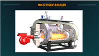
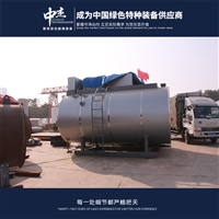
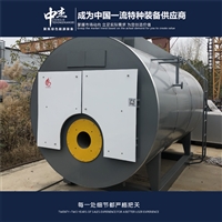
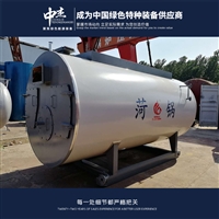

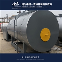
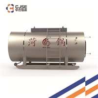
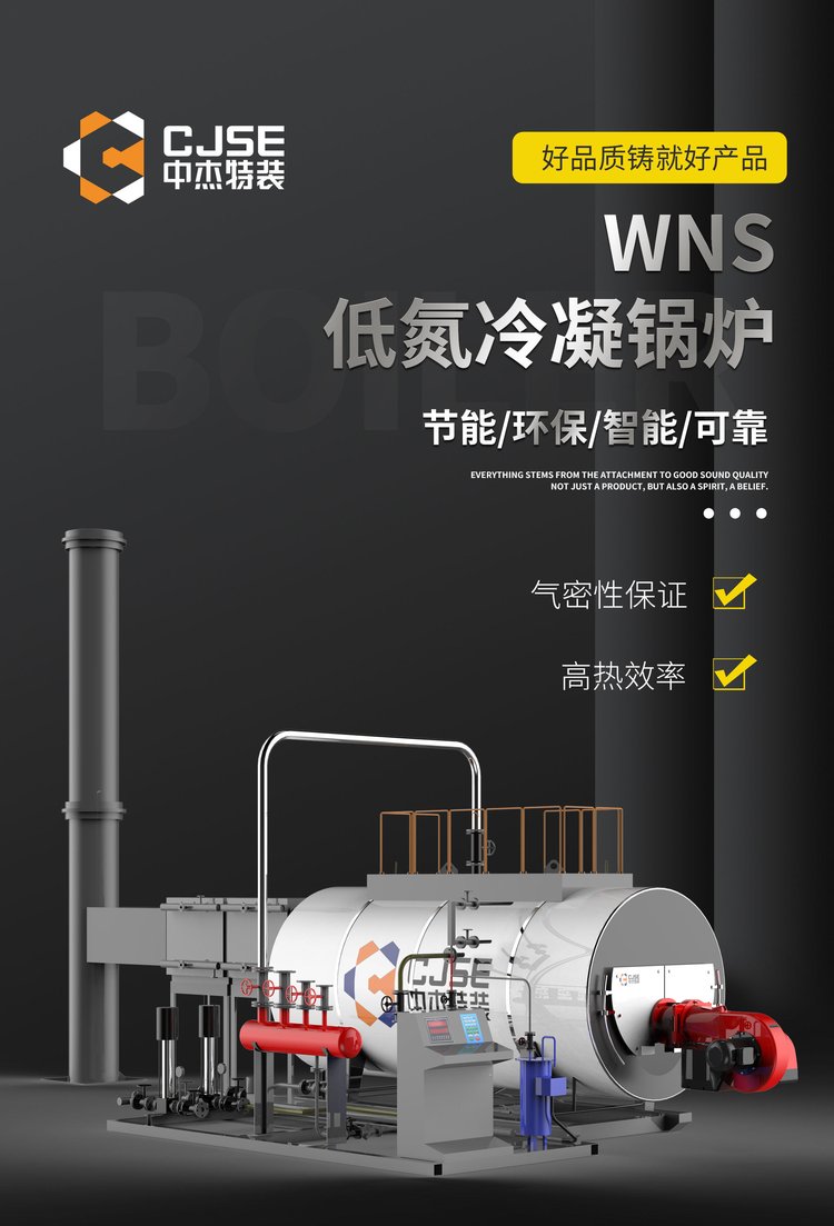
Shanxi supplies 2 tons of natural gas boiler prices and gas boiler suppliers
Category:
mechanical equipment/Industrial boilers and accessories/Gas boiler
Model:
WNS2-1.25-Q
Brand:
Zhongjie Special Equipment
Retail Price
145,000.00USD
重量
kg
- Product Description
-
Description :
Technical solution:
The construction scope and boundaries of this project are as follows: 1) Party B is responsible for the positioning and installation of the boiler body and supporting auxiliary equipment; 2) Main steam pipeline: Party B is responsible for the connection, installation, painting, and insulation of the pipeline from the boiler steam outlet to the inlet of the steam distribution cylinder in the boiler room; 3) Water supply pipeline: Party B is responsible for the installation, painting, and insulation of the water supply pipeline in the boiler room; 4) Discharge pipeline: Party B is responsible for the installation and painting of the pipeline from the boiler to the discharge pool outside the boiler room; The first party is responsible for the civil construction of the sewage tank; 5) Instrument signal pipeline: Party B is responsible for the installation and painting of the signal pipeline from the boiler to the instrument; 6) Smoke pipeline: Party B is responsible for the connection, installation, painting, and insulation of the smoke pipeline from the boiler outlet to the chimney; 7) Blowing pipeline: Party B is responsible for the installation and painting of the pipeline from the burner to the blower outlet; 8) Cable and electrical signal lines: Party B is responsible for the installation and painting of cables, signal lines, and brackets between the boiler control cabinet and the boiler and its auxiliary equipment.
The first party is responsible for pipeline installation and other matters beyond the scope mentioned above. The first party is responsible for the installation, painting, and connection of the natural gas pipeline to the burner. The first party is responsible for the construction of the civil engineering project.
Before and during the construction period of Party B, Party A shall ensure the construction conditions of Party B, ensuring the "three connections and one leveling": road, water, electricity, and site leveling. The second party shall comply with the rules and regulations of the first party, including the safety management system.
The scope of supply for this project is detailed in Chapter 7 "Supply List", and any adjustments as stipulated in the contract shall be made accordingly.
one Engineering Design Conditions
2.1 Annual average temperature: ℃
2.2 Extreme high temperature: ℃;
2.3 Extreme low temperature: ℃;
2.4 Basic seismic intensity: degree, seismic acceleration g;
2.5 Tap water: Inlet water temperature: room temperature; Water pressure: 0.4MPa (G);
2.6 Instrument air: pressure: 0.7 MPa (G); Temperature: room temperature; Dew point temperature: less than -40 ℃;
2.7 Low pressure steam: pressure: MPa (G); Temperature: ℃;
2.8 Low pressure nitrogen: pressure: 0.7 MPa (G); Temperature: 40 ℃;
2.9 Power Supply
Low voltage: 220V, single-phase;
Low voltage: 380V, 50HZ, three-phase;
2.10 Fuel: natural gas;
Low heating value of gas: KJ/Nm3
Gas temperature:~℃; Gas pressure: KPa;
two Design, Manufacturing, and Acceptance Standards
3.1 The Technical Agreement signed by both Party A and Party B;
3.2 TSG G0001-2012 Boiler Safety Technical Supervision Regulations (including Amendment 1);
3.3 TSG G0002-2010 "Boiler Energy saving Technology Supervision and Management Regulations" (including Amendment 1);
3.4 NB/T47034-2013 Technical Conditions for Industrial Boilers;
3.5 GB/T16507-2013 "Water tube boilers";
3.6 GB/T713-2014 "Steel Plates for Boiler and Pressure Vessels";
3.7 GB/T3087-2008 "Seamless Steel Tubes for Low and Medium Pressure Boilers";
3.8 NB/T47013-2015 "Non destructive Testing of Pressure Equipment";
3.9 NB/T47055-2017 "General Technical Conditions for Boiler Coating and Packaging";
3.10 JB50236-98 "Construction and Acceptance Specification for Industrial Pipeline Welding Engineering of On site Equipment";
3.11 GB50273-2009 "Code for Construction and Acceptance of Boiler Installation Engineering";
The performance of this type of burner is as follows:
1) The burner ensures stable and efficient combustion, ensuring that the flame does not deflect under operating conditions and that the flame does not directly flush the furnace wall.
2) The burner is designed as a split type, with an additional fan that can be installed in the fan room to reduce noise.
3) The burner is equipped with an observation hole and an automatic flame detection device.
4) The burner is equipped with an air inlet regulating device, and the air regulator is precision machined. The materials of the blades, shaft, and casing can withstand the high temperatures required within the design range of the burner.
5) Mechanical indicator devices are installed on the air conditioner to indicate the position of the air conditioner blades and label them with words. The operation and positioning of the air conditioner are achieved by controlling the servo motor table through the controller of the burner.
6) The burner is equipped with a flame monitor. The burner is equipped with an automatic sequential ignition device and an ignition safety protection device.
7) The combustion efficiency of the burner can reach 99.9%.
8) The burner is equipped with functions such as gas leak detection, purging, ignition, flame monitoring, flameout protection, intake pressure protection, wind pressure protection, load adjustment, etc., and is automatically controlled. This type of burner complies with national regulations.
5.4 Composition of Combustion Device
The combustion system of the burner mainly consists of the main gas supply system, ignition system, pre-treatment system, and control system.
1) The main gas supply system consists of pressure protection switches, solenoid valve groups, pressure gauge components, etc.
2) The ignition system consists of ignition electrodes, ignition transformers, etc.
3) The control system consists of a program controller, servo motors, etc.
4) Pre processing system: composed of gas filters, etc.
Automatic control of burner
Control system description
This system mainly achieves automatic control through the programmable controller configured for the burner, which mainly includes the following parts.
1) Valve group leak detection
After the burner is powered on, the program controller first sends a signal to the leak detector to conduct a leak test on the valve group to ensure that the gas valve does not leak.
Leak detection operating conditions
——The power supply of the on-site cabinet is normal
——No MFT instruction
——Leak detection command (or burner start command) has been initiated
The leak detection process is controlled by a leak detector. If there is a fault in the leak detection, the leak detection alarm will be triggered. After resetting, the leak detection will be restarted. Only after the leak detection passes, the controller will start the burner.
2) Pre blowing
Before the fuel enters the furnace for combustion (initial ignition or after boiler trip), a successful purge of the furnace must be completed to effectively eliminate any combustible gases that may accumulate in the furnace, otherwise the protection system will prevent any fuel burner from starting.
Furnace blowing is carried out when the following conditions are met and maintained
——Burner fan operation
——Gas valve fully closed
——No MFT instruction
——No fire in the furnace
——The power supply of the on-site cabinet is normal
The entire blowing process should meet the above conditions. If any condition is lost during this period, the blowing process will be interrupted. The operating personnel can only restart the blowing program after all permit conditions are re established.
3) Ignite
The ignition must meet the following conditions
——Burner fan operation
——Servo motor adjusts the burner damper to the ignition position
——No MFT instruction
——Full furnace blowing completed
——Gas pressure is normal
——Normal combustion air pressure
——The flame detector did not detect any fire in the furnace
Ignition start sequence
——The burner starts the ignition transformer, forming a stable spark between the ignition electrodes
——After the spark stabilizes, the burner opens the safety valve V1 and ignition valve Vg, and the ignition tube releases gas and ignites, forming an ignition torch. Four seconds later, the control valve V2 opens and ignites the main torch
——The burner detects flames through the assembled ultraviolet detector
——If the flame detection is normal, it indicates successful ignition
The ignition process is initiated by an electric arc (spark) to ignite the main flame. After the flame is ignited, the flame detection device must detect the flame. Otherwise, the ignition fails, the program controller alarms, and the shutdown indicator light lights up. Wait for a reset before restarting. If ignition fails, the burner will shut down and all outputs will be cut off. The shutdown alarm indicator will light up and can only be restarted after resetting.
4) Flame detection
The burner uses an ultraviolet flame detection system to detect the presence or absence of flames, and sends a signal to the controller when a flame is detected. The program controller automatically determines whether the flame signal matches the program based on the program. If it does not match, the program controller will sound an alarm and cut off all outputs. The flame detector continuously detects the entire combustion process during the blowing process, providing safety protection.
5) Load regulation
After completing the ignition program, the system enters normal operation mode, and the burner automatically adjusts the fuel and air volume, changes the main fire size, and achieves load adjustment.
 Security protection control
serial number
project
Control requirements
instruction
Remarks
one
Ignition flame failure
Sound and light alarm, locked
P
two
Main flame failure
Sound and light alarm, locked
P
three
power failure
Lock after recovery
P
four
Main air valve leakage
Sound and light alarm, locked
P
five
Gas pressure protection
Sound and light alarm, locked
P
six
Emergency stop
Cut off the control power and lock it after restoration
seven
Low pressure of combustion air
Sound and light alarm, locked
P
AfterSalesService :
Key words:- Natural gas boiler
More Products


