

Travel switch LX10-12B AC380V 10A single arm double contact JOSEF
Category:
Electrical Engineering/switch/Limit switch
Model:
LX10-12B
Brand:
Shanghai Joseph
model:
LX10-12B
Startup method:
push-button switch
rated voltage:
380V
rated current:
ten
manufacturer:
Shanghai Joseph
Retail Price
185.00USD
重量
kg
- Product Description
-
model LX10-12B
Startup method push-button switch
rated voltage 380V
rated current ten
manufacturer Shanghai Joseph
Description :
model
LX10-12B AC380V 10A single arm double contact
LX10-12
LX10-32
LX10-32 with heavy hammer
LX10-12 380V 10A
LX10-11J
LX10-12J
LX10-31 with heavy hammer
LX10-11S 2 normally closed point
LX10-12 AC380V 5A
LX10-12S explosion-proof type
LX10-22S
LX10-12S
LX101-3A
LX10-31 with heavy hammer
LX10-32 AC380V DC220V 20A
LX10-32
Product Parameters
The LX10 series travel switch is suitable for control circuits with AC 50Hz, 380V, DC 220V and below. It is mainly used as an end switch for the travel limit of the rising mechanism or as a travel switch and program control switch for the automatic circulation mechanism.
Product advantages
Compliant with IEC337-1 and GB14048. 5-93 standard
Purpose and Scope of Application
The LX10 series travel switch (hereinafter referred to as the travel switch) is used for AC 50Hz, 380V. In the control circuit of a crane with a DC 220V, it is used for endpoint protection of the mechanism stroke, and its long-term working current is 10A. The stroke switch is designed, manufactured, and inspected according to GB14048.5.
The travel switch ensures reliable operation under the following conditions:
a) The altitude shall not exceed 2000m.
b) The temperature of the surrounding medium shall not exceed+40 ℃ and shall not be lower than -50 ℃, and the daily average temperature shall not exceed+35 ℃.
c) The relative humidity of the air at the installation location shall not exceed 50% at a temperature of+40 ℃; Higher relative humidity is allowed at lower temperatures, with the average monthly temperature of the wettest month not exceeding+25 ℃ and the average relative humidity of that month not exceeding 90%. Measures must be taken to prevent condensation on the product due to temperature changes.
The travel switch is not suitable for operation under the following conditions:
a) In environments containing corrosive metals and insulating gases, vapors, or dust;
b) In an environment containing conductive dust;
c) In places with severe vibrations and jolts.
Model and its meaning

classification
The travel switch is divided into six types according to the type of operating arm:
a) The LX10-1 travel switch adopts a single roller ruler lever operating arm, which is used for translation mechanisms with relatively small inertia travel.
b) LX10-2 □ type travel switch with double roller fork lever operating arm, used for translation mechanisms with large inertia travel.
c) The LX10-3 □ type travel switch is equipped with a heavy hammer type load lever operating arm, which is used to limit the travel of the lifting mechanism.
d) The LX10-4 □ type travel switch is equipped with a three pronged operating arm, which is used as a translation mechanism for three operating positions.
e) The LX10-5 □ type travel switch is equipped with a roller hammer type operating arm, used for translation mechanisms with low speeds.
f) The LX10-6 □ type travel switch housing has roller operated arms on both sides for high-speed translation mechanisms.
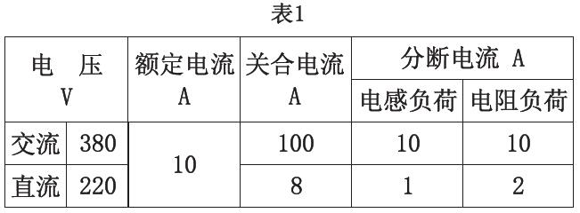
Technical data
Technical parameters are shown in Table 1.
The mechanical life of the travel switch at an operating frequency of 400/h shall not be less than 100000
The opening and closing frequency of the travel switch shall not exceed 150 times per hour.
The speed of pushing the switch operating arm shall not exceed the specifications in Table 2.

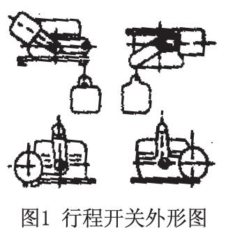
Structural Overview
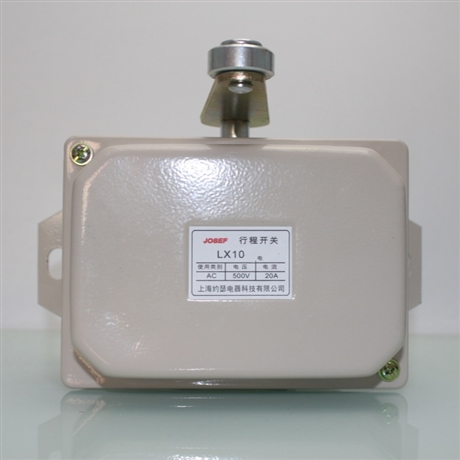
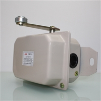
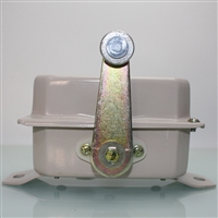
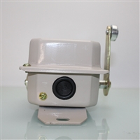
The travel switch is mainly composed of a housing, a contact group, an operating arm, a rotating shaft, a positioning component, rollers, levers, positioning springs, support components, and grounding screws. Due to different forms of protection, the shell is made of different materials. The protective shell is made of steel plate, while the waterproof shell is made of cast iron. Its appearance is shown in Figure 1, and the structural diagram is shown in Figure 2.
A set of contact groups is installed inside the travel switch housing, and the moving and stationary contacts drive the cam on the switch shaft to open and close the contacts with the rotation of the operating arm. The positioning of the manipulator arm is achieved through positioning components, positioning springs, positioning levers, and rollers.
Installation, use and maintenance
The travel switch allows installation in various positions, but LX10-31 32 51 52 is only allowed for the installation method shown in Figure 2.

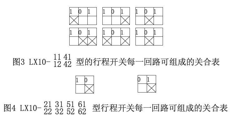
The closing condition of the contact can be changed by changing the position of the cam on the rotating shaft. When modifying, the bearing sleeve on the housing must be removed first, and then the serial shaft must be extracted before changing the position of the cam. The closing table composed of various types of stroke opening magnets is shown in Figure 3 and Figure 4.
During use, lubricating oil should be regularly applied to the friction part of the travel switch.
Ordering Instructions
Please specify when placing an order:
a) Complete product model;
b) Quantity.
AfterSalesService :
Key words:- limit switch


