
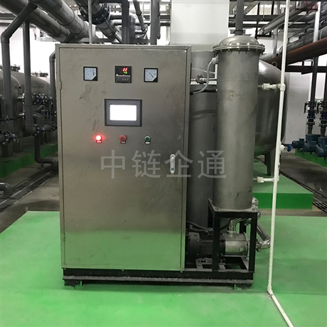


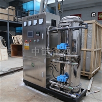
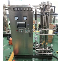
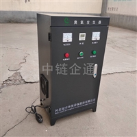
Oxygen Source Ozone Generator Air Source Ozone Generator Ozone Generator
Category:
Environmental Protection/Raw water treatment equipment/Water sterilization and disinfection equipment
Model:
GYC-K-100
Brand:
Guanyu
Retail Price
18,888.00USD
重量
kg
- Product Description
-
Description :
The circuit of the oxygen source ozone generator, air source ozone generator, ozone generator, and ozone generator consists of transistors VT1 and VT2, inductor coils L1-13, pulse transformer T, current limiting resistor R1, charging capacitor C3, bidirectional trigger diode 5, etc., forming a push-pull oscillation circuit; The filtering inductor L0, rectifier diode VD1, and filtering capacitors C1 and C2 form a half wave rectification filtering circuit. Connect the power supply, AC 220V voltage is filtered by LO, rectified by VD1, and a voltage of about 280V is generated at both ends of C1 to supply the push-pull oscillation circuit. At the moment of startup, VT1 conducts. Oxygen source ozone generator, air source ozone generator. Due to the charging effect of C3, the bidirectional trigger diode VD5 is turned off. When the charging voltage at both ends of C3 rises to 32V, VD5 is triggered to conduct, causing VT2 to conduct. During the conduction period of VT2, C3 gradually discharges, causing VT2 to turn off. After VTl is turned on, positive feedback voltage is generated on L1 and L2 under the action of pulse transformer T. This voltage is applied to the bases of VTl and VT2 respectively, causing VTl and VT2 to alternately turn on and off (i.e. when VTl is turned on, VT2 is turned off); When VT2 is turned on, VTl is turned off, and the push-pull oscillation circuit oscillates. After the push-pull oscillation circuit works, a pulse high voltage is generated on the secondary winding L6 of the pulse transformer T, causing the ozone generator VG to operate and produce ozone.
At the same time, the light-emitting diode VD7 also lights up and works. Choose 2SC2653 or BU406 silicon NPN high back voltage transistor for component selection VTl and VT2. Require current amplification factor β>; 100. VD1, VD4, and VD6 use N4007 rectifier diodes; VD5 uses DB3 type bidirectional trigger diode. All R1 and R6 are equipped with RJ-1/8W metal film resistors. L0 is a 5mH magnetic core inductor coil, which can be wound 210 turns on the skeleton with a Φ 0.25mm enameled wire; L1 is made by winding a single core plastic copper wire with a diameter of 0.2mm around the same magnetic ring, where L1 and L2 are wound 3 turns each, and L3 is wound 9 turns. The pulse transformer T can be modified using a 14 inch black and white TV output transformer. During the modification, the high voltage package is used as L6, and the low voltage package skeleton is wrapped with a ? 0.45mm enameled wire for 168 turns as L4, and a ? 0.23mm enameled wire for 4 turns as L5 (wrapped on the outer layer). Ozone generator VG is selected with models such as Z-210, Z-15, Z-20, etc. Produce and debug all electronic components except for the ozone generator VG, install them on a self-made printed circuit board, and pack them into a plastic or wooden box of appropriate size. Fix the light-emitting diode VD7 through a hole on the box surface and connect it to the ozone generator VG. As long as the components are in good condition and the wiring is correct, it can work normally when powered on.
Oxygen source Ozone generator Air source Ozone generator Ozone generator Generator and discharge tube
The core technology and equipment of the ozone system are the discharge tubes in the generator, which directly affect the operational efficiency and reliability of the equipment. The ozone generator adopts a micro gap dielectric barrier discharge design, which not only greatly improves the operating efficiency, but also increases the safety and reliability of the system's continuous operation. The technical parameters of the equipment have reached the international advanced level.
Due to the use of micro gap discharge technology, the operating voltage of the system is reduced to 6-8 kV. The oxygen source ozone generator and the air source ozone generator are much lower than the withstand voltage level of the glass tube insulation medium, effectively avoiding the occurrence of medium breakdown short circuit faults and improving operational reliability.
The modular design method adopted by the ozone generator discharge unit makes the installation, maintenance, and upkeep of the equipment easier. Under the condition of ensuring the quality of the intake air source, the maintenance free operation time of the ozone generator discharge unit can be up to 5 years.
High frequency and high voltage power supply
Unlike traditional ozone intermediate frequency (<1kHz) power supplies, high-frequency and high-voltage ozone systems use 3-6kHz high-frequency power supply technology. The combination of oxygen source ozone generator, air source ozone generator, and micro discharge gap design can effectively improve the efficiency of ozone generation, reduce the size and footprint of the generator, and thus reduce civil engineering design and investment costs. The inverter power system adopts mature high-frequency power technology, and long-term on-site operation has proven that it can ensure the stability of the system's long-term operation. After the high-frequency output is boosted by the boost system, a sine wave high voltage is generated, which is connected to the generator through a cable. Under the action of high-frequency high voltage, a cold plasma discharge is generated in the discharge gap to produce ozone.
AfterSalesService :
Key words:- Oxygen source ozone generator


