


Tide level monitoring using domestically produced self-contained tide gauges and tide gauges
Category:
Instrumentation/Special instruments and meters/hydrologic apparatus
Model:
HR8033
Brand:
Hengrui
brand:
Hengrui
model:
HR8033
type:
Submerged hydrological instrument
Processing & Customization:
No
purpose:
Water well survey
weight:
zero point three
Place of Origin:
Baoji, Shaanxi
manufacturer:
Shaanxi Hengrui Measurement and Control System Co., Ltd
Retail Price
399.00USD
重量
kg
- Product Description
-
brand Hengrui
model HR8033
type Submerged hydrological instrument
Processing & Customization No
purpose Water well survey
weight zero point three
Place of Origin Baoji, Shaanxi
manufacturer Shaanxi Hengrui Measurement and Control System Co., Ltd
Description :
HR8800SPRO Self contained/Plug in Tide Gauge (Automatic Water Level and Temperature Recorder) is an internal battery powered water level monitoring instrument that uses a pressure sensor to measure the static water pressure of a water body. The water depth value is calculated using the formula P=ρ× g × h and can be used for long-term recording of water depth (pressure) and temperature. The product contains software and hardware functional modules such as pressure sensors, temperature sensors, low-power power management, signal conditioning, large capacity FLASH memory, high-capacity long-life lithium batteries, and communication interfaces. The body adopts a titanium alloy structure, and the sensor material is tantalum, which has good corrosion resistance and is suitable for measuring water level and temperature in surface water, groundwater, and marine environments.
Features:
Self accommodating/plug-in: dual mode operation, switchable between self accommodating/online mode
High stability: using high-quality and stable pressure sensing components
High precision: water level accuracy of 0.05% F.S, resolution of 1mm; temperature accuracy of ± 0.2 °, resolution of 0.01 ℃;
Multi functional: Equipped with an internal battery and 128Mb memory, it can collect and store data at regular intervals;
All parameters are monitored and recorded simultaneously, including water level, temperature, water pressure, time, and other factors;
Signal standard: RS485 to USB serial communication;
Protection level: titanium alloy shell+tantalum sensor, IP68 protection;
Temperature compensation: full range digital calibration, full temperature range temperature error compensation;
Structural design: The built-in battery allows users to replace it themselves without affecting the product's sealing;
1.2 Application Fields
Monitoring of groundwater level and water temperature data
Urban flood control liquid level monitoring
Real time monitoring of water levels in reservoirs and dams
Monitoring of Tide Levels in Oceans, Lakes, and Surface Runoff
Hydrological monitoring stations
Real time monitoring of liquid level inside the tank
On site liquid level monitoring of industrial control systems
Sensitive components
High stability long-term use without drift
range
0-20m H2O; 0-30m H2O; 0-50m H2O; 0-80m H2O
0-100m H2O; 0-200m H2O; 0-300m H2O
Other ranges can be customized
Water level accuracy
0.05%F.S(0~50℃)
Water level resolution
1mm
stability
0.05% F.S/year
overload
2X F·S
temperature accuracy
±0.2℃
temperature resolution
0.01℃
Internal battery life
10 years (recorded once/60 minutes)
storage capacity
16MB built-in storage, capable of recording 1000000 pieces of data (time+temperature+pressure+water level)
Real-time clock
< ± 5 minutes/year
sampling interval
1 second to 4 hours (if>59 seconds, the minimum interval unit is minutes)
Temperature compensation range
0~50℃
Operating Temperature
-10~80℃
power supply voltage
External voltage: DC5-30V (typical 24V)
Internal battery: 2.7-3.6VDC
power protection
Anti reverse connection, anti 2KV surge, overvoltage protection
output method
RS485 to USB, download data to computer through adapter
measuring medium
Non corrosive fluid medium for tantalum/titanium alloy materials
Shell material
titanium alloy
Protection level
IP68
weight
About 300 grams (excluding cables)
Environmental vibration:
Endure the vibration test specified in GB/T9359
free fall
Endure the drop test specified in GB/T9359
electromagnetic environment
Complies with GB/T17626.8 Level 3
Mean time between failures
Not less than 30000 hours
Chapter Installation and Debugging
2.1 On site installation
Before installation and use, please carefully read the "HR8800S PRO Tide Gauge User Manual" and be sure to install and debug according to the requirements of the user manual.
1. Precautions for use
1) The bottom of the product should be as far away from the bottom of the water body as possible and installed vertically to avoid blockage of the product probe inlet by bottom sludge and debris, ensuring measurement accuracy;
2) It is strictly prohibited to remove the water guide plug for use, and it is strictly prohibited to touch the pressure diaphragm of the product with hard objects;
3) The product should be slowly placed in the logging or other application site, and it is strictly prohibited to throw it randomly to avoid water hammer damage to the pressure sensor;
4) It is advisable to measure the amplitude of the water body within the range of 70% to 90% of the product's full range to ensure sufficient resolution, accuracy, and necessary safety overload capacity;
2. Electrical connection
The output interface of HR8800S PRO tide gauge is RS485 digital output, and the product is connected to the adapter through a four core waterproof connector.
3. Wiring Definition
1) The wiring definition of the reader is shown in Figure 2-1:
2) LEMO connector wiring definition
serial number
line color
definition
one
red
5V+
two
blue
RS485+
three
green
RS485-
four
Huang
GND
2.2 Product Debugging
1. Product testing
Before formal debugging, the HR8800S PRO upper computer software should be used for testing. Only one product is allowed to be connected during testing. The specific testing method is as follows:
1). The tide gauge is connected to the adapter through a four core aviation plug, and the adapter is connected to the USB port of the PC;
2). Run the HR8800S PRO upper computer software, select the COM port where the adapter is located, and click the red button to connect the device. If the button turns green, it indicates a successful connection (see Chapter 4 for specific instructions on using the upper computer software);
3). Click the 'Find Device' button on the upper computer software, and the device address will display the Modbus device communication ID. At this point, the 'Read Current Data' button will become clickable. Click this button to read a piece of data. The collected temperature, pressure, and water level data can be seen in the dashboard or data table above the software, as shown in Figure 2-2, indicating that the product function is normal and installation and debugging can continue;
Figure 2-2 HR8800S PRO upper computer software interface
2. Product debugging
After the product testing is completed and the function is confirmed to be normal, the product can be debugged and set up. This product supports RS485 serial port data collection, Flash capacity check, Flash data reading, and Flash storage clearing. At the same time, this product supports the standard ModBus RTU protocol, and users can configure the product through the upper computer or use other tools that support the ModBus RTU protocol to read data and set parameters.
According to the product agreement, users can perform read and write operations on product registers to access function registers, data registers, and status registers. The main operations are as follows:
1) Basic parameter settings: device communication address settings, sampling interval, etc;
2) Calibration parameter settings: density setting of the tested liquid, current time calibration, etc;
3) Test data reading: reading detection parameters such as temperature, pressure, and water level;
4) Status register reading: Read the status register to understand the operating status of the product.
Note: For detailed information on product software usage and parameter settings, please refer to Chapter 4
Step 5.1: Open the upper cover and clamping ring, as shown in Figure 5-1
5.2 Open the battery compartment cover, as shown in Figure 5-2:
5.3 Remove the original battery and install a new one. Please pay attention to the positive and negative poles during installation, as shown in Figure 5-3.
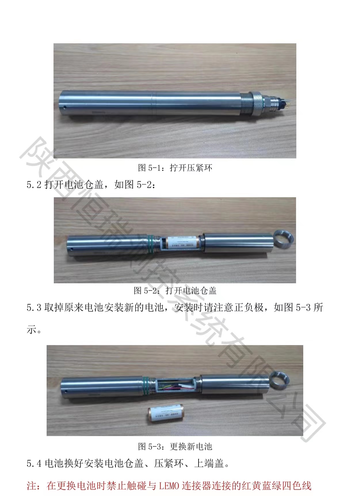
5.4 Replace and install the battery compartment cover, compression ring, and upper end cover.
Note: Do not touch the red, yellow, blue, and green wires connected to the LEMO connector when replacing the battery;
Electricity consumption: 1 second takes about 20 days; 1 minute is about 2 years; 10 minutes is about 5 years; 1 hour is about 10 years
AfterSalesService :
Key words:- Domestic self-contained tide gauge
More Products


