


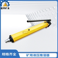


YT4-10A hydraulic pusher for coal mine underground, Jiabang hydraulic slider
Category:
mechanical equipment/Hydromechanical/Hydraulic engineering machinery
Model:
YT4-10A
Brand:
Jiabang
brand:
Jiabang
model:
YT4-10A
Item Number:
2-65
type:
tracked
material:
iron
Overall dimensions:
1055×135×210
Product Specifications:
thirty-two
Retail Price
600.00USD
重量
kg
- Product Description
-
brand Jiabang
model YT4-10A
Item Number 2-65
type tracked
material iron
Overall dimensions 1055×135×210
Product Specifications thirty-two
Description :
YT4-10A hydraulic pusher for coal mine underground, Jiabang hydraulic slider
1、 YT4-10A hydraulic sliderintroduction
The YT4-10A single hydraulic pusher is a manual sliding tool designed to meet the needs of coal mine blasting and general mining working faces. This is used in conjunction with several models of flexible scraper conveyors such as SGW40T and SGW80T, as well as other small scraper conveyors, to adapt to different forms of coal mining and meet the requirements of users to a greater extent. It can achieve significant results in reducing accidents, civilized production, and cost reduction. At the same time, this type of pusher can be used as a small hydraulic press, widely used for equipment maintenance, accident handling, and some occasions that require pushing and pushing.
Strong adaptability, good maneuverability, easy operation, high efficiency, easy maintenance, safe and reliable, can save a lot of investment compared to hydraulic jacks with centralized oil supply, and is economically cost-effective
2、 YT4-10A hydraulic sliderprinciple
The YT4 type single hydraulic slider is mainly composed of a double acting plunger pump, a combination valve, a directional valve, and a double acting oil cylinder. 1. When the force lever is pressed down, the pump plug of the plunger pump moves downward, creating negative pressure in the upper chamber of the pump. The oil in the mailbox is sucked into the upper chamber of the pump through the inlet pipe and the inlet valve of the combination valve. At the same time, the oil in the lower chamber is squeezed by the pump plug, and the oil outlet valve of the combination valve is opened to enter the rear chamber of the oil cylinder through the high-pressure chamber of the directional valve, pushing the piston and extending the piston rod group. The oil in the front chamber of the oil cylinder is squeezed out by the piston, flows through the oil filling pipe, and the low-pressure chamber of the directional valve is discharged back to the mailbox. When the power lever is lifted, the lower chamber of the pump plug absorbs oil, and the pressure oil in the upper chamber enters the rear chamber of the oil cylinder through the combination valve and directional valve, continuing to push the piston and piston rod group to extend. When the piston rod extends to a stroke of 600mm (800mm), the Y-shaped rubber ring on the piston passes over the damping hole located at the front of the oil cylinder. The pressure oil in the rear chamber of the oil cylinder is connected to the return oil circuit in the front chamber of the oil cylinder through the damping hole, and the oil is discharged back to the mailbox through the return oil pipe, achieving stroke unloading and stopping the movement of the piston, providing safety protection. At this point, there will be a feeling of lightness when manipulating the pressure handle, and the handle will become heavier after unloading the empty test. 2. Recycling: The oil pumped out by the plunger pump with a 90 degree rotation of the directional valve enters the front chamber of the oil cylinder through the directional valve and the return pipe, while a small amount of oil enters the rear chamber of the oil cylinder through the damping hole. However, these oils are directed directly to the oil tank through the directional valve and do not generate pressure. Additionally, due to the damping effect of the holes, the pressure in the front chamber of the cylinder increases and the piston begins to recover. When the Y-shaped rubber ring on the piston returns and crosses over the damping hole, the oil circuit to the damping hole is cut off, and the piston rod assembly recovers normally. The oil in the rear chamber of the cylinder flows back to the oil tank.

IIIYT4-8A hydraulic sliderinstallation and arrangement
In order to evenly push the conveyor, based on on-site experience, a fast hydraulic pusher is installed at the head and tail of the machine, and at every 10m in other sections. During installation, the first step is to move the slider to the coal wall side. The second step is to fix the connecting clip of the pusher to the groove on the old pond side of the SGW-40T-40 and DSJ-650-30 conveyors. The third step is to connect the pusher and the connecting clip with a pin and make them perpendicular to the conveyor. The pusher is located between two individual hydraulic supports.
5、 Before using the fast hydraulic pusher to move the mining face conveyor, the floating coal in front of the conveyor is first cleaned to reduce the pushing resistance. Secondly, the handle on the force plate is adjusted to clamp the arc-shaped force points on the support legs on both sides of the pusher. Thirdly, the hydraulic valve handle is operated to supply liquid to the rear chamber of the pusher cylinder, causing the cylinder to extend and push the conveyor forward. Fourthly, when the conveyor is fully pushed in place, the hydraulic valve is operated in reverse to supply liquid to the front chamber of the pusher cylinder, causing the cylinder shaft to retract into the cylinder and drive the cylinder forward to its original position.


AfterSalesService :
Key words:- Hydraulic slider
More Products


