

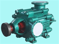

Hunan D-type multi-stage centrifugal pump
Category:
chemical industry/pump/centrifugal pump
Model:
D500-57*6
Brand:
Zhongda water pump
Retail Price
89,620.00USD
重量
kg
- Product Description
-
Description :
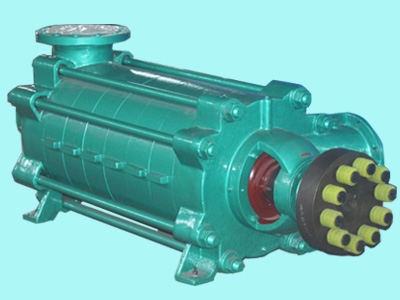
I. Overview
The D-type pump is a single suction multi-stage, segmented centrifugal water pump suitable for water supply and drainage in mines, factories, and cities. For conveying water that does not contain solid particles or abrasives, suspended solids, or other liquids with physical and chemical properties similar to water. The temperature of the transported liquid is between -20 ℃ and 8 ℃. The MD type single suction multi-stage wear-resistant pump is made by changing the material based on the original D-type pump. This pump is suitable for neutral mineral water with a solid particle content of no more than 1.5% (particle size less than 0.5 mm) and similar other sewage. The temperature of the conveyed medium is not higher than 80 ℃, and it is suitable for steel plants, mine drainage, sewage transportation and other occasions. Its performance parameters and external installation dimensions are the same as those of the D-type pump.
2、 Model Material Description
150D (MD)30 ×5
Model: D-multi-stage, segmented centrifugal water pump
MD multi-stage wear-resistant pump
150- Pump suction diameter (e.g. m)
30- Single stage lift of 30 meters
31-5- The pump stage is 5 stages
Material List:
If users have special requirements for the material of wear-resistant pumps, they can negotiate with the manufacturer.
3、 Structural description
The pump housing is mainly composed of bearing body, front section, middle section, rear section, guide vanes, etc., which are connected as a whole by bolts. The centerline of the front suction inlet is horizontal, and the centerline of the rear discharge outlet is perpendicular to the horizontal.
2. Rotor section
The rotor part is mainly composed of a shaft and components such as impellers, shaft sleeves, and balance disks installed on the shaft. The components on the shaft are fastened with flat keys and shaft sleeve nuts to integrate with the shaft. The entire rotor is supported on the pump housing by bearings at both ends, and the number of impellers in the rotor section depends on the number of stages of the pump.
3. Bearing section
This type of pump has two types of bearings: sliding bearings and rolling bearings, depending on the model, both of which do not bear axial forces. The pump should allow the rotor part to move axially in the pump housing during operation, and radial ball bearings should not be used. The bearings used in various types of pumps are shown in the table
4. Sealing of the pump
The sealing surfaces between the front, middle, and rear sections of the pump are sealed with one pound key lubricating grease. The rotor and fixed parts are sealed with sealing rings, guide vane sleeves, packing, etc. When the wear of the sealing rings and guide vane sleeves has affected the operation and performance of the pump, they should be updated in a timely manner
When using this type of pump, the position of the packing ring should be placed correctly. The distribution of the packing and packing ring for each type of ammonia is shown in Table 2. The tightness of the packing must be appropriate, so that the liquid can leak out drop by drop (8-10 drops/minute is recommended).
5. Balance mechanism
The balancing mechanism consists of a balancing ring, a balancing sleeve, a balancing disk, etc. The balancing mechanism is used to balance the axial force of the pump.
4、 Assembly and disassembly of pumps
1. Pump assembly
The quality of the assembly of this type of pump directly affects whether the pump can operate normally, and affects the service life and performance parameters of the pump; The vibration and noise that affect the unit should be noted during assembly, including the following points:;
a、 The concentricity of the fixed parts after assembly is ensured by the manufacturing accuracy and assembly quality of the parts. The machining accuracy and surface roughness of the parts should be guaranteed, and collisions or scratches are not allowed. Molybdenum disulfide used as sealant should be clean. The screws and bolts used for fastening should be evenly stressed. b、 The alignment between the impeller outlet channel and the guide vane inlet channel is ensured by the axial dimensions of each component. The quality of the neutral flow channel directly affects the performance of the pump, so the size of the pump cannot be adjusted arbitrarily.
c、 After the pump assembly is completed and before packing is installed, rotate the pump rotor by hand to check whether the rotor rotates flexibly inside the housing and whether the axial movement meets the specified requirements.
d、 After the above inspection meets the requirements, add packing to the shaft seals at both ends of the pump, paying attention to the relative position of the packing ring in the packing chamber. 2. Disassembly of pump
a、 Disassembly should be carried out in the reverse order of assembly, and the manufacturing accuracy of the parts should be strictly protected from damage during disassembly. B、 When disassembling the through rod, each middle section should be cushioned to prevent loosening and sinking of the middle section joints, which may cause the shaft to bend.
5、 Pump installation
When installing this type of pump, in addition to meeting the general installation technical requirements, the following points should also be noted:
1. When installing the motor and water pump in combination, the end shaft of the pump coupling should be pulled out outward, and an additional 2-3m end clearance value should be left to ensure the axial clearance value between the pump and motor couplings.
2. The axis lines of the pump and motor should be on the same horizontal straight line. 3. The pump can only withstand its own internal forces and cannot withstand any external forces.
6、 Starting, running, and stopping of the pump
start;
1. Before starting the pump, the rotor should be turned first to check if it is flexible. 2. Check if the motor direction is consistent with the pump direction.
3. Close the pump outlet gate valve and pressure gauge plug, and use the conveyed liquid or vacuum system to remove the suction pipe and air inside the pump body (empty operation is strictly prohibited).
4. Check the tightness of the bolts connecting the pump and motor, as well as the safety situation around the pump, to prepare the pump for start-up.
5. Start the pump, wait for the pump to operate normally, open the pressure gauge plug, slowly open the pump outlet gate valve, and control the given head of the pump according to the outlet pressure gauge reading.
Run:
1. This type of pump relies on an internal balancing mechanism to balance axial force. The balancing device has balancing liquid flowing out, and the balancing liquid is connected to the suction section through a balancing water pipe or a short pipe is set at the balancing chamber. The balancing liquid flows out of the pump through the short pipe. To ensure the normal operation of the pump, the balancing water pipe is not allowed to be blocked.
2. The rolling bearings of this type of pump do not have cooling devices, and the temperature rise of the bearings reflects the assembly quality of the pump. The temperature rise of the bearings should not exceed 35 ℃ above the ambient temperature, and the temperature should not exceed 75 ℃.
3. The rotor of this type of pump has a certain axial movement during operation, and the clearance value between the end faces of the motor and water pump couplings should be ensured.
4. During the operation of the pump, the wear of the impeller, sealing ring, guide vane sleeve, balance disc, and shaft sleeve should be regularly checked. If the wear is too large, it should be replaced in a timely manner.
5. Develop detailed operating procedures based on specific situations during use. parking
Before parking, the pressure gauge plug should be closed first, and the outlet gate valve should be slowly closed. After the outlet valve is closed, the motor should be stopped.
7、 Possible pump malfunctions and solutions (see Table 3)
fault
reason
solve
1. The water pump does not absorb water. The pointers of the pressure gauge and vacuum gauge jump violently.
Insufficient water injection into the water pump: air leakage in the suction pipeline or instrument
Inject water into the water pump again; Tighten or block the leak.
2. The water pump does not absorb water, and the vacuum gauge shows high vacuum.
The bottom valve is not open or has been clogged; The water absorption resistance is too high, and the water absorption height exceeds the allowable value.
Correct or modify the bottom valve; Clean or replace the suction pipe to reduce the suction height.
3. There is pressure at the outlet of the water pump on the pressure gauge, but the water pump still does not discharge water.
The resistance of the outlet pipe is too high, the rotation direction is incorrect, the impeller is clogged, and the water pump speed is not enough.
Check or shorten the water outlet pipe, change the motor direction, clean the impeller, and increase the speed of the water pump shaft.
4. The traffic is lower than expected.
The water pump is clogged, the sealing ring is worn too much, and the water pump
Insufficient rotational speed
Clean the water pump and pipes, change the sealing ring, and increase the speed of the water pump shaft.
5. Excessive power consumption.
The packing gland is too tight, the impeller is worn, and the water supply of the pump increases.
Loosen the packing gland or remove the packing and square it, replace the impeller, and adjust the gate valve to reduce the flow rate.
6. The water pump produces abnormal sounds during operation, and the flow rate decreases until it stops producing water.
The gate valve is opened too much, the resistance of the suction pipe is too high, air infiltrates at the suction point, the suction height is too high, and the temperature of the conveyed liquid is too high.
Adjust the gate valve to reduce the flow rate; Check the suction pipeline and bottom valve to reduce the suction height; Tighten or block the leaking area; Reduce the temperature of the liquid.
7. Pump vibration.
The pump shaft and motor shaft are not on the same centerline
Align the axis centerlines of the water pump and motor.
8. The bearing is overheated.
No oil or dirty oil; The water pump shaft and the motor shaft are not on the same centerline.
Inject or replace oil, align the axis centerline.
AfterSalesService :
Key words:- multistage centrifugal pump


