


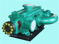
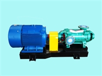


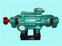
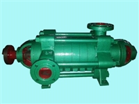
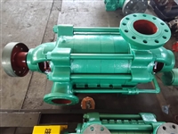
DF corrosion-resistant centrifugal pump 46-50 * 3 composition
Category:
mechanical equipment/pump/water pump
Model:
DF46-50*4
Brand:
Hunan Zhongda University
Retail Price
45,620.00USD
重量
kg
- Product Description
-
Description :
Product Overview
The casing of a stainless steel multi-stage pump is made of stainless steel. Multiple impellers are mounted on a pump shaft and connected in series to work together. When the liquid passes through each impeller in turn, it is subjected to centrifugal force, and the energy increases in turn, obtaining the head. Stainless steel multi-stage pumps are mainly composed of four parts: stator, rotor, bearings, and shaft seals. The main causes of vibration during operation are bolt loosening, rotor imbalance, etc. The solution is to tighten bolts, straighten bearings, etc.

compose
1. The stator part of a stainless steel multi-stage pump mainly consists of a suction section, a middle section, a discharge section, and guide vanes. Generally, stainless steel multi-stage pumps have horizontal suction and vertical upward discharge; The stainless steel multi-stage pump for boilers has both the inlet and outlet facing vertically upwards.
2. The rotor part of a stainless steel multi-stage pump is mainly composed of a shaft, impeller, balance plate, and shaft sleeve. The axial force is balanced by the balance plate.
3. Stainless steel multi-stage pump bearings are mainly composed of bearing bodies, bearings, and bearing covers;
4. The stainless steel multi-stage pump shaft seal adopts soft packing seal, mainly composed of sealing box body, packing, water blocking ring, etc. on the inlet section and tail cover. Generally, the water seal of stainless steel multi-stage pumps comes from the pressure water inside the pump. The water seal of the stainless steel multi-stage boiler pump is sourced from external water supply
working principle
Stainless steel multi-stage pump is a type of centrifugal pump that relies on the rotation of the impeller to obtain centrifugal force. As a result, the material is extracted when the gas density reaches the working range of the mechanical vacuum pump, gradually achieving high vacuum.
An appropriate amount of water is contained in the stainless steel multi-stage pump body as the working fluid. When the impeller rotates clockwise, water is thrown around by the impeller. Due to the centrifugal force, the water forms a closed ring of approximately equal thickness determined by the shape of the pump chamber. The lower inner surface of the water ring is exactly tangent to the impeller hub, and the upper inner surface of the water ring is just in contact with the top of the blade (in fact, the blade has a certain insertion depth inside the water ring). At this point, a crescent shaped space is formed between the impeller hub and the water ring, and this space is further divided into several small chambers equal to the number of blades by the impeller.
If starting from the lower part of the impeller at 0 °, the volume of the small chamber increases from small to large when the impeller rotates 180 ° before, and is connected to the suction port on the end face. At this time, gas is sucked in, and when the suction is completed, the small chamber is isolated from the suction port; When the impeller continues to rotate, the small chamber becomes smaller, compressing the gas; When the small chamber is connected to the exhaust port, the gas is discharged outside the pump.
In summary, stainless steel multi-stage pumps rely on changes in pump chamber volume to achieve suction, compression, and exhaust, making them variable volume centrifugal pumps.
Vibration solutions
There are six main reasons for the large vibration of multi-stage pumps during operation:
1. The coaxiality between the motor shaft and the pump shaft exceeds the specified limit;
2. Pump shaft bending or rotor imbalance;
3. There are foreign objects or friction in the impeller;
4. Friction occurs between the rotor and the shell;
6. The base bolts are loose.
Solution to vibration during multi-stage pump operation:
1. Find the correct coupling;
2. Straighten the shaft and perform dynamic balancing on the rotor;
3. Clean or replace the impeller;
4. Adjust the gap between the rotor and the housing;
5. Adjust the clearance or replace the bearing;
6. Tighten the base bolts;
piping
In order to avoid the weight of pipelines and valves, as well as the force and torque generated by pipeline thermal stress, exceeding the allowable external load of the pump inlet and outlet, pipe racks must be installed on the suction and discharge pipelines of the pump. The allowable load of the pump tube port should be provided by the pump manufacturer.
2. For pumps with vertical inlet or outlet, in order to reduce the force on the pump pipe mouth, a pipe rack must be installed above the pipe mouth, and its plane position should be as close to the pipe mouth as possible. The pipeline can be supported and suspended by the longitudinal beam of the pipe gallery, so the pump is often arranged under the pipe gallery.
In order to improve the suction performance of the pump, the suction pipeline of the pump should be shortened as much as possible, with as few bends as possible (large curvature radius should be used for bends), in order to reduce pipeline resistance loss. To prevent cavitation of the pump, the suction pipe of the pump should avoid the bladder shaped part where gas accumulates as much as possible. If it cannot be avoided, a double suction pump should be installed in the bladder shaped part. In order to avoid cavitation of the bidirectional suction horizontal centrifugal pump, the double suction pipes should be symmetrically arranged to ensure even flow distribution on both sides. The vertical pipeline is directly connected through an elbow, but the axis of the pump must be perpendicular to the plane where the elbow is located. At this point, the imported piping should be as short as possible, with the elbow connected to the reducer and then connected to the inlet flange. Under other conditions, the weight of the valve on the inlet and outlet pipeline of the non-metallic pump should not be less than that of the pump body before the pump inlet. A pipe rack should be set up to prevent damage to the pump body and the pipeline before and after the valve is twisted when opening and closing the valve.
4. The exhaust pipeline of the steam reciprocating pump should have fewer bends, and a discharge pipe should be installed at the location where condensation water may accumulate. If the venting volume is large, a muffler should also be installed. The steam inlet pipeline should be equipped with a condensate discharge pipe before the steam inlet valve to prevent water from hitting the cylinder.
When the distance between the centerline of the pump outlet and the centerline of the pipe gallery column is greater than 0.6m, the swing check valve on the outlet pipeline should be placed in a horizontal position, and it is not allowed to install a clean valve on the valve cover at this time.
When the pipeline is placed above the pump and motor, in order not to affect the lifting of the lifting equipment, the pipeline should have sufficient height. Pipelines transporting corrosive liquids should not be arranged above the original moving equipment.
The net distance from the bottom of the pipeline in the lower part of the pipe gallery to the floor should not be less than 4m to meet maintenance requirements.
When the pipeline is placed above the pump body, the clearance height from the bottom of the pipe to the ground should not be less than 2.2m.
AfterSalesService :
Key words:- DF corrosion-resistant centrifugal pump


